What Is a Remote IO Module and How Does It Work?
A Remote Io Module connects field devices to a control system, carrying signals from sensors and commands to equipment. Picture a temperature sensor beside a motor, wired to a compact module in a cabinet. The module reads the sensor’s electrical signal, converts it into usable data, and sends it across an industrial network. A controller can then respond, while operators see equipment status on a screen. Small device. Important job.
John Rinaldi, an industrial networking author, offers a useful principle that can be paraphrased this way: “Understand the communication path before selecting the connection.” That reminder matters because a Remote Io Module is more than a box of terminals. Its inputs and outputs, protocol, power requirements, and environmental rating must suit the installation. A dusty plant floor, for example, places different demands on a module than a clean control room. Wiring layout matters, too.
How does the signal travel? A sensor produces an input; the module samples it and reports the value to a controller or supervisory system. In the reverse direction, the module receives a command and switches an output, such as a relay controlling a valve. Timing, configuration, and network reliability affect whether this exchange works as intended. Not every setup is simple. A module may appear compatible on paper, yet require careful testing in the real system. This guide explains the components, signal flow, common architectures, and selection factors behind remote I/O. The details matter—and they deserve a second look before installation.
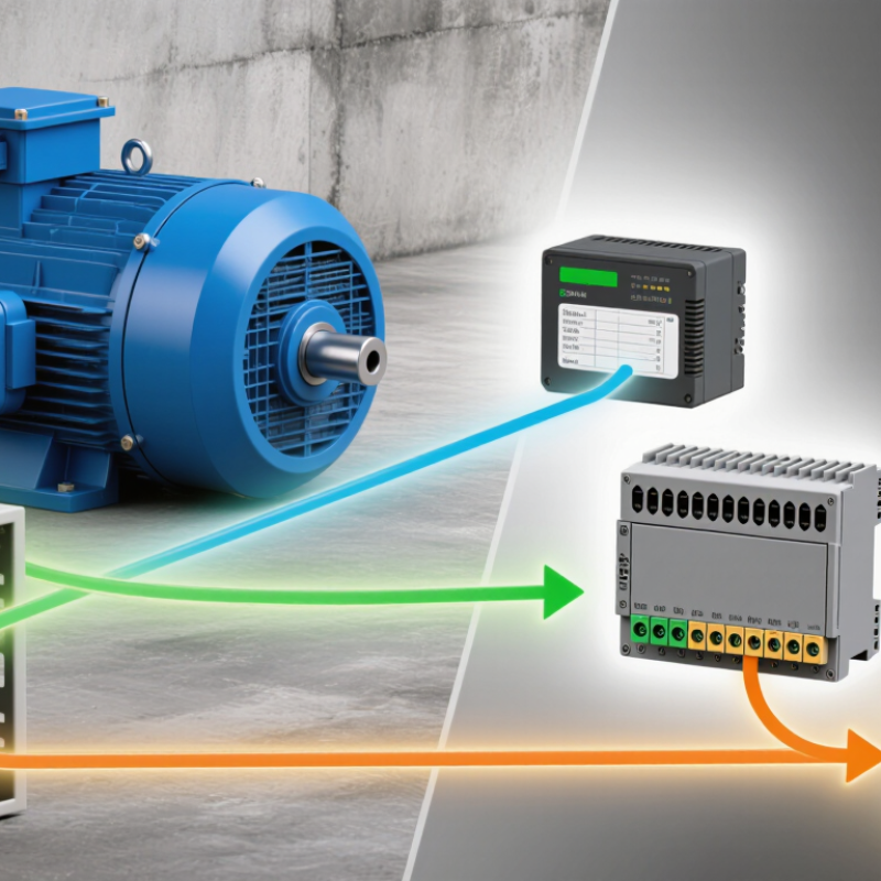
What a Remote I/O Module Does in a Distributed Control System
In a distributed control system, remote I/O modules connect field devices to controllers across the plant. They are installed near equipment, so sensor and actuator wiring can stay relatively short. A module reads inputs from devices such as a pressure transmitter or level switch, then sends those values over an industrial network. The controller uses the data to run control logic. Small signals matter.
Output channels carry commands back to devices, including valve positioners and motor starters. Depending on the design, a module may handle digital signals, analog signals, or both. It converts electrical input into data the controller can interpret, and converts output commands into signals field equipment can use. Network delays and update rates deserve attention. A fast-moving process may need tighter response times than a slow storage tank.
Remote I/O can make a large system easier to expand and maintain, but it does not remove the need for careful engineering. Engineers need to check channel types, wiring limits, environmental conditions, and communication-loss behavior. Diagnostics can help identify a broken wire or failed channel, though they cannot explain every process fault. That is not always tidy. A well-documented layout helps technicians trace a signal from the device, through the module, to the controller without guessing.
Inside the Module: 24 VDC Power, Signal Channels, and Network Interfaces
A remote I/O module links field devices to a control system over a network. Inside, a 24 VDC supply powers the module’s electronics and, on some models, connected sensors. The supply needs a stable voltage; a loose terminal or overloaded circuit can cause intermittent readings. That small detail matters.
Signal channels receive inputs or drive outputs. A digital input may detect whether a limit switch is open or closed, while an analog channel can read a changing value, such as a pressure transmitter’s current signal. Output channels can switch a valve or relay, within their rated limits. Each channel has configuration requirements, including signal type and range. Mixing them up can produce plausible-looking, but wrong, data. Not magic.
The network interface packages channel data for exchange with a controller or supervisory system. Depending on the design, it may use an industrial Ethernet protocol or another field network. Status indicators can help identify power, communication, or channel faults, though they do not explain every cause. In a real cabinet, cable routing and grounding may be less neat than the wiring diagram suggests. I would verify the module’s wiring, channel settings, and network configuration before trusting a reading.
From Field Signals to PLC Data: 4–20 mA Inputs and Digital I/O
What Is a Remote IO Module and How Does It Work?
From Field Signals to PLC Data: 4–20 mA Inputs and Digital I/O
A remote I/O module connects sensors and actuators near the equipment to a PLC over an industrial network. It converts field signals into data the controller can read, reducing long cable runs back to the control cabinet. For a 4–20 mA input, the module measures loop current and scales it to an engineering value, such as tank level or pressure. A reading of 4 mA often represents the live-zero point; a much lower reading may indicate a fault, depending on configuration. Small differences matter.
Digital I/O handles simpler on-or-off states. A digital input might report whether a guard switch is closed, while a digital output can energize a relay or indicator. Channel type, voltage range, and wiring must match the field device. Noise matters. In real cabinets, wiring diagrams can look cleaner than the wiring itself, so check grounding, polarity, and isolation before troubleshooting the network.
Tips: Confirm each channel’s signal type and scaling in the PLC configuration. For current loops, verify the power source and return path, then compare the module reading with a meter. Label wires at both ends. A loose terminal can mimic a failed sensor.
How Remote I/O Communicates via PROFINET, EtherNet/IP, or Modbus TCP
Remote I/O moves sensor and actuator signals to a field module near the equipment. The controller exchanges data with that module over an industrial Ethernet network. A pressure reading can travel from a pipe-mounted sensor to the controller, while an output returns to open a valve. Fewer long copper runs can simplify cabinet wiring. But communication still depends on sound network design.
With PROFINET, EtherNet/IP, or Modbus TCP, the module packages input and output values into network messages. PROFINET and EtherNet/IP commonly support cyclic data updates, so controllers receive values at configured intervals. Modbus TCP uses client-server requests and register-based data, which can suit simpler monitoring tasks. Configuration differs: engineers map device names, IP addresses, assemblies, or registers, depending on the protocol. Small errors matter. A shifted register can make a healthy sensor look faulty.
The 2024 Industrial Network Market Shares report estimated PROFINET at 23% and EtherNet/IP at 21% of newly installed industrial network nodes. Modbus TCP accounted for about 5%. Those figures show adoption, not that one protocol fits every plant. Check update time, diagnostics, existing infrastructure, and recovery behavior before choosing.
In commissioning, watch the live values while switching a real input; paper mappings can look perfect. That test is easy to overlook.
How to Compare Channel Count, Isolation, IP Rating, and Response Time
A remote I/O module links sensors and actuators near a machine to a controller over a field network. It converts signals such as a 4–20 mA reading or a switch contact into data the controller can use. Outputs carry commands back to valves, relays, or other devices. This can reduce long home-run wiring, but network delays and cable conditions still matter.
Compare channel count with the actual points needed, including spare capacity for planned changes. A 16-channel unit may look efficient, yet mixed analog and digital signals can require separate module types. Not always. Check whether channels are isolated individually, in groups, or not at all. Isolation helps limit noise and fault transfer, especially when sensors use different power supplies. Read the wiring diagrams; a headline specification may hide important boundaries.
The IP rating describes protection against dust and water, not resistance to every chemical, temperature, or washdown routine. An IP67 enclosure may suit brief immersion, but connectors and installation details affect real protection. Response time also needs context: input filtering, network update rate, and controller scan time all contribute to the delay. Check the whole path. For a fast-moving process, test the complete setup under realistic load rather than choosing from one response-time figure. Some specifications are easy to compare; their assumptions are not always obvious.