Empowering Engineering Excellence: Innovate, Elevate, Deliver.
Choosing an Rf Divider manufacturer is not a logo-comparison exercise. It is a decision about signal balance, isolation, frequency coverage, and dependable delivery. A component that looks ideal on a catalog page may behave differently once installed in a crowded rack or tested across a wide temperature range. Small details matter.
Global buyers should compare more than insertion loss. Check amplitude and phase balance, port isolation, connector options, operating bandwidth, power handling, and test documentation. Ask how the manufacturer verifies performance across production batches. A clear datasheet helps; a traceable test report helps more. Lead time, customization support, and communication during design reviews can also shape a project’s real cost.
The market includes established RF suppliers and specialized manufacturers serving narrower frequency bands or application needs. The right shortlist depends on whether the system supports telecom infrastructure, radar, laboratory testing, or another RF platform. There is no universal winner. That is worth remembering.
A credible expert quotation should come from a named professional and a verifiable interview, publication, or company source. No such source was provided for this topic, so assigning a quotation to an expert here would risk misrepresentation. This guide instead focuses on practical evaluation criteria and the questions buyers can ask before choosing an RF Divider supplier. Compare specifications against the actual operating environment, not just the headline numbers. A careful review may take longer, but it can reveal trade-offs that a polished product page leaves out.
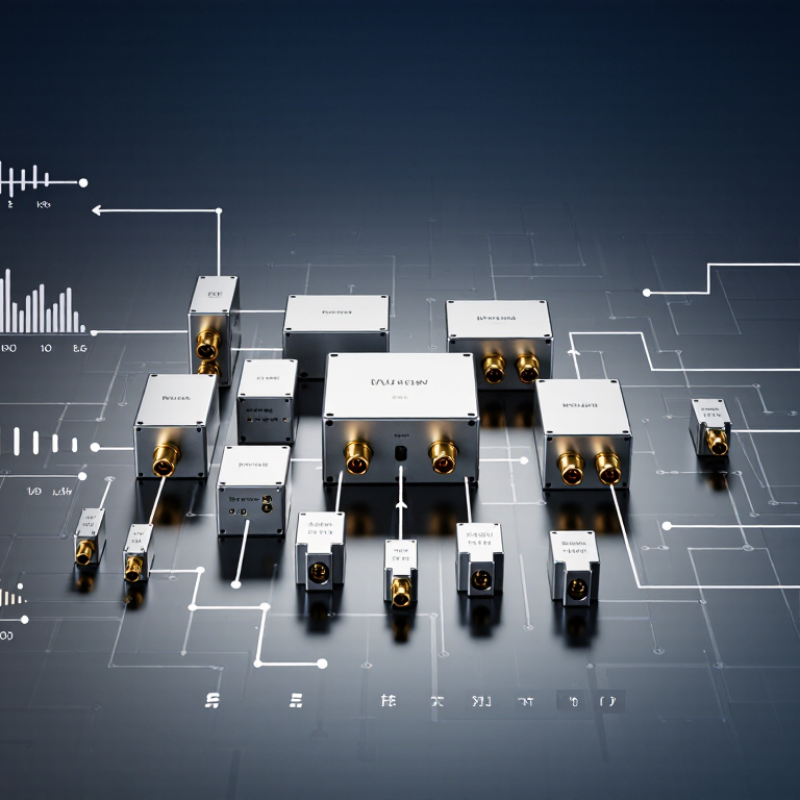
RF Power Dividers split one signal into two or more paths while maintaining controlled impedance. In many systems, each port is designed for 50 Ω. This helps limit reflections when connected to properly matched cables and equipment. A mismatch can raise return loss and disturb the signal at the load. Small details matter.
Inside a divider, transmission lines and resistive elements guide power from the input to the outputs. A Wilkinson design is common for equal splits and good output isolation, though it needs a defined frequency range. Resistive dividers can cover broad bandwidths, but dissipate more power. Hybrid dividers may also provide a set phase relationship between outputs. Not always needed. The intended signal path should guide the choice.
For a practical check, compare operating frequency, power rating, split ratio, insertion loss, isolation, and connector type. A vector network analyzer can reveal poor matching; terminate unused ports with suitable 50 Ω loads during measurements. Also check the specified temperature range and mounting conditions. A neat datasheet cannot show every installation problem. Long cables, tight enclosures, or loose connector interfaces can change measured performance, so verify the assembly as it will actually be used.
For global RF buyers, 3.01 dB is the ideal split loss of an equal two-way divider; 6.02 dB is ideal for four ways. These figures come from 10 log10(N), where N is the number of equal output ports. They describe power division alone, not the full loss of a real component. IEEE Std 149-2021 provides recognized guidance for measuring microwave components, including practices relevant to checking divider performance.
On a bench, compare measured insertion loss with the ideal baseline, then check amplitude balance, phase balance, return loss, and isolation across the specified frequency band. A four-way unit may show more than 6.02 dB because conductors, dielectrics, connectors, and internal matching networks dissipate or reflect energy. Small differences matter. At the upper end of a band, a connector or short cable can also affect a reading. Ask suppliers for test conditions, calibration details, and measured results—not just a headline loss figure. The ideal number is useful, but it is not the whole story. Real measurements can be messy, and that deserves a second look.
When comparing RF divider manufacturers for global projects, read excess loss alongside the ideal splitting loss. A two-way divider already loses power through its split; excess loss shows additional dissipation. Ask whether figures are typical or guaranteed, and check the test frequency and connector configuration. Numbers need context.
Isolation matters when one output sees a changing load. Better isolation can reduce interaction between branches, but results depend on frequency and termination quality. VSWR describes impedance matching at the ports. A high VSWR may increase reflections and complicate system calibration. Request measured plots across the operating band, not just one favorable point. A bench check can expose details a tidy datasheet misses.
Confirm the specified frequency range, then verify performance near both band edges. Power ratings need equal care: distinguish average input power from peak power, and review thermal conditions. A compact divider in a warm enclosure may behave differently from one tested on an open bench. I still find power assumptions easy to overlook. Ask suppliers for test methods, tolerances, and environmental limits, then compare like with like. A slightly imperfect specification sheet is not automatically a deal-breaker, but unanswered measurement questions deserve attention.
Global buyers should compare RF divider manufacturers by topology and frequency coverage, not catalog size alone. Useful portfolios include two-, four-, and eight-way Wilkinson dividers, resistive splitters, and connector or enclosure options. Wilkinson designs typically offer lower insertion loss, while resistive designs can provide broad bandwidth in compact packages. Check amplitude and phase balance, isolation, return loss, power rating, and operating temperature. These details matter when a divider feeds several receiver paths inside a crowded rack. Some portfolios cover sub-1 GHz and common cellular bands; others add microwave or millimeter-wave models. Confirm whether a stated range is continuous or divided into separate bands.
The 3GPP TS 38.104 specification defines 5G NR frequency ranges from 410 MHz to 7.125 GHz for FR1, and 24.25 to 71 GHz for FR2. A single divider rarely spans those extremes with consistent performance. Ericsson’s June 2024 Mobility Report projected 5.6 billion 5G subscriptions by the end of 2029, around 60% of global mobile subscriptions. That growth makes band-specific variants increasingly relevant to network testing and infrastructure. Look for test plots across the exact operating band, not only a headline frequency range. Real installations are less tidy. Cable loss, connector choice, and temperature can change measured results, so datasheet figures deserve a closer look.
Comparison basis: This brand-neutral guide summarizes common RF power-divider product types and industry frequency-band boundaries. Frequency spans shown as example catalog ranges are indicative, not specifications for any particular manufacturer or product.
| Product Portfolio Segment | Common RF Coverage | Typical Divider Configurations | Typical Construction or Features | Common Applications | Buyer Checks |
|---|---|---|---|---|---|
| HF and VHF power dividers | HF: 3–30 MHz; VHF: 30–300 MHz. Individual products usually cover a specified portion of these bands. | 2-way, 3-way, and 4-way; impedance-matched designs are selected for the stated operating range. | Coaxial or connectorized assemblies; some designs use transformer-based or resistive networks. | Broadcast systems, communications, laboratory distribution, and antenna test setups. | Check the exact frequency limits, port match, insertion loss, isolation, and power rating. |
| UHF and lower microwave dividers | UHF: 300 MHz–3 GHz. Example broadband catalog spans may include portions of 0.5–6 GHz. | 2-way, 3-way, 4-way, and 8-way Wilkinson-style or other specified architectures. | Often available in coaxial connectorized formats; options may include matched terminations and multiple output ports. | Wireless infrastructure, public-safety communications, GNSS-related test systems, and RF laboratories. | Confirm connector type, amplitude and phase balance, isolation, and whether the stated range includes all ports. |
| L- and S-band dividers | L band: 1–2 GHz; S band: 2–4 GHz. These standard band labels meet at 2 GHz. | Commonly 2-way through 8-way; larger port counts depend on design and performance requirements. | Coaxial products are common; compact surface-mount or custom assemblies may be available for particular designs. | Satellite navigation, radar, telemetry, and wireless or test instrumentation systems. | Review insertion loss per path, input/output VSWR, power handling, and phase tracking requirements. |
| C- and X-band dividers | C band: 4–8 GHz; X band: 8–12 GHz. Example product ranges may cover selected portions, such as 4–12 GHz. | 2-way, 4-way, and other port counts subject to bandwidth and isolation requirements. | Typically precision coaxial assemblies; waveguide implementations are also used in suitable system designs. | Radar, satellite communications, microwave links, and measurement systems. | Check performance across the full specified band, connector or waveguide interface, and thermal limits. |
| Ku-band dividers | Ku band: 12–18 GHz; products generally cover a defined sub-band or a wider specified range. | Usually 2-way or 4-way for compact, broadband coaxial designs; other configurations are application-specific. | Precision connectorized assemblies; some applications use waveguide components. | Satellite communications, radar, and high-frequency test and measurement. | Verify connector frequency rating, phase balance, insertion loss, and environmental qualification. |
| K- and Ka-band dividers | K band: 18–27 GHz; Ka band: 27–40 GHz. Specialized products may cover selected portions of these ranges. | Most commonly 2-way or 4-way in compact high-frequency designs; configuration depends on bandwidth and power needs. | Precision coaxial or waveguide construction; mechanical tolerances and interface quality are especially important. | High-frequency satellite links, radar, millimeter-wave research, and advanced test systems. | Confirm usable bandwidth, connector or waveguide standard, calibration reference, and power derating. |
| Custom and application-specific dividers | Defined by the system requirement; designs may target a narrow band or combine multiple specified bands. | Custom output counts, unequal power splits, or integrated divider/combiner functions may be specified. | May include custom packaging, cable assemblies, environmental sealing, or integrated terminations. | Special-purpose communications, phased-array systems, aerospace, defense, and industrial instrumentation. | Request a complete datasheet and confirm qualification, traceability, test limits, and production availability. |
Selection note: A divider’s performance is product-specific. Compare the datasheet’s full operating range, insertion loss, isolation, VSWR, amplitude and phase balance, power handling, connector interface, and environmental ratings before purchase.
When comparing RF divider manufacturers, treat the datasheet as a test plan, not a sales summary. Check insertion loss, amplitude balance, phase balance, isolation, and return loss across your actual frequency band. Excellent typical values may hide weaker performance near band edges. Ask whether figures are typical or guaranteed, and review the stated test conditions. Small details matter.
Confirm that material, environmental, and quality documents apply to the exact configuration you plan to buy. Request traceable lot records and verify that the offered part number matches the tested design. Then check lead times, minimum order quantities, and lifecycle status in writing. A fast sample is useful. Repeatable production matters more. Availability can change.
Technical support can reveal how well a supplier understands the product. Share your frequency range, impedance, power level, connector needs, and board constraints. Ask for measurement plots or evaluation guidance, and listen for clear explanations of limitations. Vague answers are a reason to verify claims with bench measurements. Comparisons also have gaps when suppliers use different test setups, so headline numbers alone can mislead.