Empowering Engineering Excellence: Innovate, Elevate, Deliver.
A seized bearing can turn a routine repair into a costly delay. The right Hydraulic Puller applies controlled force while keeping the workpiece stable. The wrong one may slip, damage a shaft, or exceed its rated capacity. Capacity alone is not enough. Reach, jaw spread, cylinder stroke, attachment fit, and available clearance all matter.
SKF’s Bearing Damage and Failure Analysis guidance estimates that improper mounting contributes to about 16% of premature bearing failures. That figure covers mounting practices broadly; it does not mean a puller alone prevents bearing damage. Still, it shows why careful removal and installation deserve attention. Picture a bearing tight against a shaft shoulder, with little room behind its inner race. A puller with insufficient reach may not seat properly, even if its force rating looks impressive. Easy to miss. Check the manufacturer’s load limits and setup instructions before applying pressure. Keep the pulling line aligned, inspect contact points, and stop if the assembly shifts or binds. Real workshops are rarely ideal; rust, awkward access, and worn parts complicate the choice. This guide presents seven practical tips for matching puller design and capacity to the job, while recognizing that tool selection cannot replace sound judgment or a controlled setup.
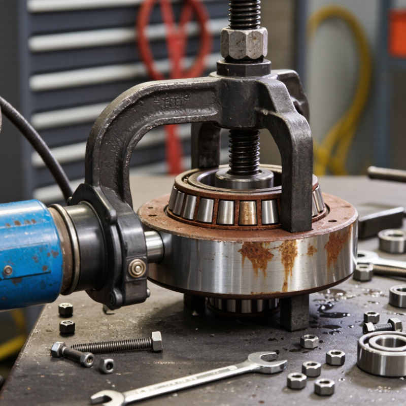
Before choosing a hydraulic puller, define the job: what component must move, and what holds it in place? A bearing, gear, pulley, or sleeve may look similar, but each can need a different grip and support arrangement. Note the shaft diameter, component width, available clearance, and whether the part is seized or merely a tight fit. Small details matter. A jaw that contacts a thin edge can slip or damage it.
Inspect the assembly before applying force. Identify a solid pulling surface and check nearby seals, housings, threads, and wiring. Estimate the required reach and pulling capacity from the component and service information; do not treat the tool’s maximum rating as the target load. A useful shop-floor habit is to mark the intended contact points before fitting the puller. It catches awkward setups early. The U.S. Bureau of Labor Statistics reported about 2.6 million nonfatal injury and illness cases in private industry in its 2023 Survey of Occupational Injuries and Illnesses. Those figures are not specific to puller work, but they underline why controlled setups and clear work areas matter. I still pause when a component’s support point is uncertain. Guessing is not a method.
A hydraulic puller’s capacity should match the force needed to break the part free, not merely its size. Estimate cylinder force with pressure multiplied by effective piston area. In practical units, force in kilonewtons equals pressure in bar multiplied by area in square centimetres, then divided by 100. ISO 4413:2010, the hydraulic-fluid-power safety standard, emphasizes controlling pressure-related hazards. Do not guess.
For example, a cylinder operating at 700 bar with a 20 cm² piston area produces about 140 kN, or 14.3 metric tonnes-force. This is theoretical cylinder output, not automatically a safe working load for the complete puller. Check the tool’s rated capacity, operating-pressure limit, and the manufacturer’s load instructions. The lowest-rated component sets the limit.
Real parts may need extra force to overcome corrosion, tight fits, or uneven contact. These are easy to underestimate. Include a documented allowance for breakaway load, but do not invent a universal safety factor; follow the tool’s technical guidance and site procedure. Keep the puller aligned with the shaft, and use a calibrated pressure gauge or load cell when the required force is uncertain. A slightly rusty bearing can change the job. Reassess rather than simply increasing pressure.
7 Hydraulic Puller Tips for Choosing the Right Tool?
Choose the Right Jaw Style, Reach, and Spread
A puller works best when its jaws match the part, not just the available space. Two-jaw models can fit into narrow gaps, while three-jaw designs often center more evenly around a hub or bearing. For internal removal, check that the jaws are designed to grip from inside. A poor fit can slip or damage the component. Small details matter.
Measure reach from the jaw contact point to the shaft or surface where the forcing screw will bear. Then compare the required spread with the puller’s stated range; do not assume the jaws will open safely to their limit under load. Leave room for the jaws to sit squarely behind the part. Check the tool’s rated capacity and keep the ram aligned with the shaft. If the puller tilts, stop and reposition it rather than adding pressure. I still double-check these measurements, especially when the part is partly hidden. It is easy to misjudge. A little extra reach may help, but oversized jaws can crowd nearby parts and reduce stable contact. A snug, centered setup is usually the better choice.
Choose the jaw style, reach, and spread to suit the job, then confirm the puller’s rated capacity and setup requirements.
Capacity reference: The chart converts example ratings in US short tons-force to kilonewtons using 1 short ton-force = 8.896 kN. These are conversion examples, not recommended capacities for a particular job. Select a puller based on the load and the tool maker’s rating.
Match the hydraulic system to the place where the puller will work, not just the force it must deliver. A dusty repair bay can contaminate fluid through open couplings and careless storage. ISO 4406:2021 classifies hydraulic-fluid cleanliness using particle counts in three size bands: 4, 6, and 14 micrometres. That detail matters. Keep couplings capped, inspect hose connections, and follow the power-unit maker’s filtration requirements. A clean-looking reservoir can still contain harmful particles.
Temperature and moisture change the choice, too. Cold oil may flow slowly, while heat can shorten fluid and seal life; check the unit’s specified operating range before use. For outdoor jobs, consider sealed connections, protected hoses, and a power pack suited to rain, dust, or grit. In a washdown area, corrosion-resistant surfaces may be worth the extra cost. ISO 4413 sets general safety requirements for hydraulic systems, including their operating conditions. Use its guidance alongside the puller’s instructions, and inspect hoses for cracks or abrasion before pressurizing. Small details matter. I still find it easy to underestimate where the pump will sit during a job. Keep it stable, accessible, and away from pinch points.
A safe hydraulic puller starts with a careful look, not a quick pump. Check the ram body for dents, the hose for cuts or bulges, and couplers for leaks. Inspect jaw tips, pins, and threads for wear or cracks. Small details matter. A slight oil film around a fitting may signal a developing leak, not harmless dirt. Do not guess. If damage is unclear, pause and have the tool assessed before use.
Confirm that the puller’s rated capacity suits the load and that its reach and jaw opening fit the part. The jaws should seat evenly behind the component, with the ram centered on the shaft. A crooked setup can shift under pressure. Never extend the tool beyond its specified stroke or compensate with improvised extensions. Fit matters.
Before applying pressure, secure the workpiece and keep hands clear of pinch points. Wear eye protection, and stand outside the likely path of a slipping part. Release pressure before repositioning jaws or changing attachments. Follow the tool’s operating instructions, especially for pressure limits and maintenance intervals. Even a careful check can miss hidden wear, so record recurring leaks or unusual resistance and arrange a closer inspection.
| Tip | What to Check | Why It Matters | Practical Check |
|---|---|---|---|
| 1. Match the puller’s capacity to the job | Confirm the puller’s rated pulling capacity and do not exceed the rating of any component in the setup. | Overloading can damage the tool or workpiece and may cause parts to fail under force. | Estimate the load required for the application and select a tool rated for that work. Follow the tool’s instructions and rating plate. |
| 2. Check reach and spread | Measure the distance from the shaft end to the part being removed, and the diameter across the part’s gripping points. | The puller must reach behind the part and open wide enough to grip it securely. | Compare the measurements with the puller’s specified reach and maximum spread before applying force. |
| 3. Choose a compatible jaw arrangement | Check whether the job calls for external or internal pulling, and confirm the jaw shape and number suit the part. | Correctly positioned jaws help distribute the load and reduce the risk of slipping or damaging the part. | Make sure all jaws seat evenly on a suitable gripping surface and do not rest on fragile edges or unsupported areas. |
| 4. Verify hydraulic-system compatibility | Check that the cylinder, pump, hoses, and couplings are designed to work together and that their pressure ratings are compatible. | Mismatched components or pressure ratings can create leaks, equipment damage, or an unsafe setup. | Use the specified hydraulic fluid and connection type, and never connect components beyond their stated pressure limits. |
| 5. Inspect the tool before use | Look for cracked or bent parts, damaged threads, leaking seals, worn hoses, loose couplings, and a damaged ram or tip. | Wear or damage can compromise the puller when it is under load. | Remove questionable equipment from service and have it inspected or repaired before use. |
| 6. Check safety features and safeguards | Look for features such as a pressure-relief valve, a secure locking or retaining arrangement, and any supplied shield or guard. | These features can help control pressure and reduce exposure to moving or released parts, but they do not replace safe work practices. | Confirm safety features are present and functional. Follow the instructions for the specific tool and use suitable eye and face protection. |
| 7. Plan a stable, controlled pull | Check that the puller is centered on the shaft, the jaws are seated evenly, and the workpiece is supported. | Misalignment or an unstable setup can cause the puller to slip, bind, or release parts unexpectedly. | Apply force gradually, keep people clear of the line of pull, and release hydraulic pressure before adjusting or removing the tool. |