Empowering Engineering Excellence: Innovate, Elevate, Deliver.
Choosing the right Self Locking Connector starts with the conditions it must survive, not the shape of its latch. Will it sit beside a vibrating motor, inside a damp enclosure, or behind a panel that is difficult to reach? These details change what “secure” means. A connector that clicks firmly on a workbench may still loosen when cable strain pulls sideways.
Check the essentials. Confirm the required current, voltage, contact count, wire gauge, operating temperature, and mating-cycle rating. Then examine the locking style, sealing level, materials, and release method. Gloves, limited clearance, and frequent servicing matter. So does the cable itself. A tight lock cannot compensate for poor strain relief.
A practical rule: “Choose the connector for the failure you cannot afford.” This is an editorial engineering principle, not a verified quotation from a named expert. A credible named expert quotation should be added only after its source is confirmed; inventing one would weaken trust. That may feel less polished. It is more reliable.
This guide will help compare connector types, interpret specifications, and avoid common selection errors. Look closely at the mating pair, not just the plug. Confirm compatibility with the exact receptacle, then test the assembly under realistic vibration and handling. Small checks matter. A missed latch dimension or an awkward release tab can turn a sound design into a frustrating installation.
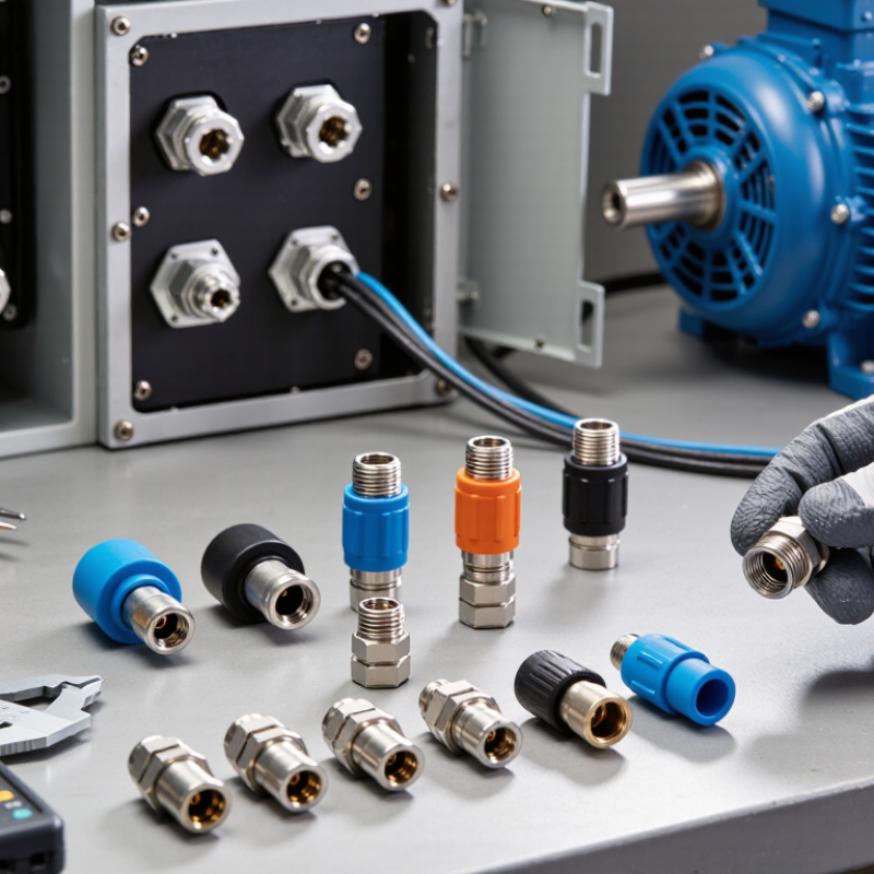
A self-locking connector uses a mechanical feature to resist accidental separation after mating. Depending on its design, a spring-loaded sleeve, latch, or set of locking fingers holds the two halves together. As the connector is pushed into place, guides help align the parts, and the locking feature moves into position. The connection should feel secure, not forced.
To disconnect some designs, the user pulls back a release sleeve before separating the halves. Others use a different release motion, so the product’s instructions matter. The lock keeps the connector engaged; it does not automatically guarantee a good electrical contact or a watertight seal. Those depend on the contact layout, seals, and correct assembly. A click can be helpful, but it is not proof by itself.
It is easy to focus only on how firmly a connector locks. In practice, consider how often it will be mated, whether gloves will be used, and whether dust or vibration is likely. Check that the release is accessible and that the locking parts show no damage. A connector that is difficult to release may seem reassuring at first. It can also slow maintenance, or tempt someone to pull the cable instead of using the release. That detail deserves a second look.
Before selecting a self-locking connector, write down the circuit’s actual demands. Record the operating voltage, continuous current, and any brief current peaks during startup. A connector rated only for normal running current may overheat under repeated surges. Check the wire gauge and contact resistance, too. Small details matter.
Then map the environment around the connection. Will it face water spray, dust, oil, vibration, or frequent temperature changes? A connector near a pump may need a seal that stays compressed, while one inside a warm enclosure needs suitable temperature limits. Look beyond a general “water-resistant” description. Confirm the specified ingress rating and test conditions match your installation. Measure twice.
Locking strength deserves a practical check. A cable pulled sideways can loosen a connection even when the latch feels firm by hand. Consider cable weight, movement, mating cycles, and available space for release. In a tight cabinet, a secure connector can be awkward to service. I’ve seen designs chosen from a drawing alone, then reconsidered after the first maintenance visit. That is not always avoidable; real routing can surprise you. Allow room for the cable bend, and verify that the seal, contacts, and housing suit the same operating conditions.
How to use this chart: These illustrative project temperature envelopes show the operating range to define for different applications; they are not connector ratings or universal standards. Before selecting a connector, also specify maximum operating voltage (including transients), continuous and peak current, circuit count, and any signal or data requirements. Confirm the chosen connector’s ratings and suitability for the actual temperature, ingress, vibration, and chemical exposure conditions.
Self-locking connectors prevent accidental separation, but the locking style must suit the actual motion and service environment. Threaded couplings resist vibration and suit equipment that is rarely disconnected. Bayonet locks engage with a short turn, useful when access is tight. Push-pull designs allow quick changes, but check their release collars cannot catch on nearby cables. Small detail. It matters.
Material choice affects weight, corrosion resistance, and electrical performance. Copper-alloy contacts generally provide good conductivity; plated surfaces can help limit oxidation, though plating quality and wear matter. Polymer shells are light and insulating, while metal shells can offer added mechanical protection. Do not assume metal is always better: moisture, chemicals, and dissimilar metals may create problems. A catalog photo is not enough.
The IEC 60512 series provides test methods for electrical connector performance, including mechanical operation and retention. Ask for relevant test results, mating-cycle ratings, and vibration data for the specific connector configuration. Grand View Research estimated the global electrical connectors market at USD 84.4 billion in 2023, underscoring how widely these components are used; market size, however, does not prove a design is suitable. Check cable diameter, current rating, sealing, and whether gloves make the latch awkward to operate. I would still test the chosen connector on the actual assembly. Specifications can miss awkward details.
A self-locking connector should fit the whole system, not just the cable. Compare contact size, pin arrangement, voltage, current, and wire gauge before ordering. Check the mating connector too; two housings can look identical while their keyways differ. A mismatch may prevent full engagement or damage a contact. Small details matter.
Read the safety ratings for the actual working conditions. Check temperature range, vibration resistance, sealing level, and rated mating cycles, then allow for real operating loads. A connector’s rating does not automatically protect the full assembly; the cable, contacts, and enclosure also matter. In a damp or dusty area, confirm how the rating applies when the connector is mated. I would not rely on appearance alone.
Installation needs can rule out an otherwise suitable part. Measure the space around the connector, including room for fingers, tools, and cable bend radius. Confirm whether crimping or another specified termination method is required, and use the correct tooling. After assembly, inspect the contacts and gently pull the cable to check retention. The lock should engage clearly, though some designs feel less obvious than expected. Verify the maker’s instructions before installation, especially when vibration or frequent servicing is involved.
| Selection Dimension | What to Check | How to Choose | Useful Data or Reference |
|---|---|---|---|
| Connector and contact compatibility | Connector family, contact arrangement, pin count, gender, keying, and mating interface. | Confirm that both halves are specified to mate with each other. Matching appearance or pin count alone does not establish compatibility. | Compare manufacturer drawings, part numbers, contact layouts, and keying details. |
| Electrical requirements | Operating voltage, current per contact, circuit count, and whether contacts are carrying power, signals, or both. | Select a connector whose published ratings meet the application requirements. Account for contact count, ambient temperature, wire size, and any stated derating. | Use the product datasheet’s voltage and current ratings; do not assume a rating applies to every contact simultaneously. |
| Safety and compliance | Required approvals, insulation properties, flammability performance, and suitability for the end product. | Check the applicable product and installation requirements, then verify certificates or declarations for the exact connector model. | IP classifications are defined by IEC 60529. UL 94 is a plastics flammability test method; a material rating is not, by itself, approval of the complete connector or equipment. |
| Environmental protection | Exposure to dust, water, moisture, chemicals, UV, vibration, and temperature extremes. | Choose environmental ratings for the assembled connection, including cable entry, seals, and mating condition. Check whether protection applies only when mated. | Read the specified IP rating and operating-temperature range in the datasheet. An IP rating does not define chemical resistance or vibration performance. |
| Locking mechanism | Threaded coupling, bayonet coupling, push-pull latch, or another positive-retention design. | Match the mechanism to the expected vibration, connection frequency, access, and required release method. Confirm that the lock is fully engaged during installation. | Use the manufacturer’s stated retention, coupling, and mating-cycle data; there is no single performance value that applies to all locking connectors. |
| Wire and cable fit | Conductor size, cable diameter, insulation type, shielding, and strain-relief requirements. | Verify that the contacts accept the conductor size and termination method, and that the backshell or gland accommodates the cable diameter. | Check the specified wire-size range, cable-entry range, strip length, and approved crimp or solder instructions. |
| Installation space and access | Panel cutout, mounting depth, connector orientation, clearance for coupling, and tool access. | Compare the connector drawing with the available enclosure space and confirm that installers can reach and release the locking feature. | Use the manufacturer’s dimensional drawing, including panel thickness, mounting dimensions, and recommended clearance. |
| Assembly and maintenance | Required tools, termination skill, inspection steps, and frequency of connection or disconnection. | Choose a termination and lock style that can be assembled, inspected, and serviced using the tools and procedures available at the installation site. | Follow the specified assembly instructions and mating-cycle limit; replace parts that are damaged or fail inspection. |
| Final verification | Correct mating, secure locking, wiring continuity, polarity, and absence of visible damage. | Inspect the completed connection and test the circuit before placing the equipment into service. | Use the equipment’s approved inspection and test procedure. Never connect or disconnect equipment under load unless its documentation explicitly permits it. |
Note: Ratings and compatibility are model-specific. Verify the exact connector documentation and applicable regulations before purchase or installation.
A self-locking connector should be chosen for the job it will perform, not just its appearance. Start with the system’s voltage, current, wire size, and expected mating cycles. Then consider the environment: vibration, dust, moisture, temperature swings, and limited access can all affect performance. A connector that feels secure on a workbench may loosen when mounted near a vibrating motor. Small details matter.
Check how the locking feature engages and releases. Can a technician confirm it is fully seated by touch or sight? Is there enough clearance for gloved hands? Review the connector’s documented ratings, but also check whether they apply to the assembled cable and installation. A rating alone is not the whole story. I have seen selection discussions focus heavily on pull strength while overlooking cable strain and mounting support. That is an easy gap to miss.
Validate the choice in conditions close to actual use. Assemble sample connectors with the intended wire, tooling, and enclosure, then inspect retention and continuity after repeated mating and exposure to expected vibration or temperature changes. Record what was tested. If the connector is difficult to inspect or service, that matters too. Real installations are rarely as tidy as drawings suggest. A small trial can reveal a poor fit before the design is fixed.