Empowering Engineering Excellence: Innovate, Elevate, Deliver.
A Crawler Drive Motor is the component that turns hydraulic or electrical power into track movement. It helps a crawler machine push through mud, gravel, and uneven ground while maintaining controlled speed. The basic idea is straightforward. The engineering is not. Torque, gearing, seals, and heat all affect how reliably the machine moves.
Inside a hydraulic system, pressurized fluid enters the motor and drives its rotating group. The motor’s output passes through a reduction gearbox, which increases torque at the sprocket. The sprocket then pulls the track links forward. Picture a loaded excavator climbing a damp slope: steady track movement depends on more than motor power. The gearbox, hydraulic supply, and track condition matter too. Small leaks or overheating can become costly clues. They deserve attention.
This introduction will explain the motor’s main parts, operating cycle, and role in a crawler undercarriage. It will also cover performance factors, common symptoms, and practical maintenance checks. One limitation matters: no source article or verifiable expert quotation was provided, so I cannot responsibly attribute a direct quote to a named specialist. A useful engineering summary is: “A crawler drive motor converts available power into controlled track force, while its heat and response reveal how the system is performing.” It is concise, perhaps too neat. Real machines are messier, and diagnosis should consider the whole drive system.
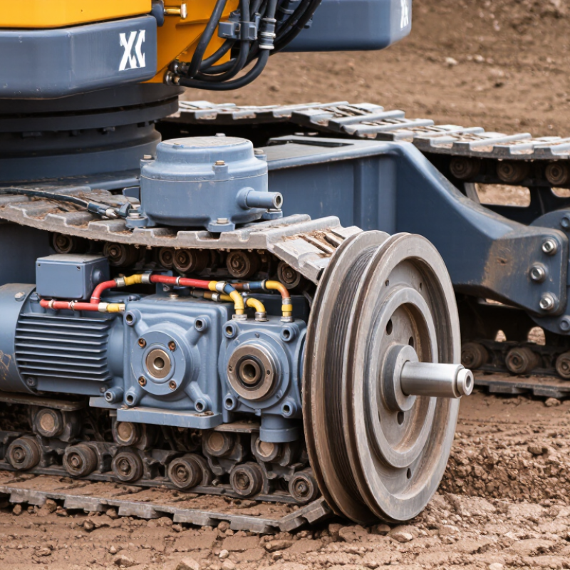
A crawler drive motor is the component that supplies motion to a tracked machine. It converts hydraulic pressure or electrical power into rotation. That rotation turns a reduction gearbox and drive sprocket, which pulls the track chain around its rollers. The track then pushes against the ground, moving the machine forward or backward. That is its job.
The motor also helps control travel speed and turning. On many machines, separate motors drive the left and right tracks. Slowing or reversing one side lets the machine pivot in a tight space. The gearbox reduces motor speed while increasing torque, which matters when a loaded machine climbs a slope or crosses soft soil. Some drive assemblies also include brakes to hold the machine when travel stops. Exact layouts vary, so the machine’s service information is the best guide.
Heat, leaks, unusual noise, or sluggish movement can point to trouble, but none proves the motor is faulty. A blocked filter or worn track may produce similar symptoms. A quick visual check can mislead. Measure pressure or electrical supply, inspect the track system, and compare results with the equipment specifications before replacing parts. That extra check is easy to skip. It can also prevent a costly mistake.
What Is a Crawler Drive Motor and How Does It Work?
Key Components of a Crawler Drive Motor
A crawler drive motor turns hydraulic or electrical power into track movement. In many machines, the drive unit combines a hydraulic motor with a planetary reduction gearbox. The motor spins quickly, while the gearbox reduces speed and increases torque. That extra turning force helps move heavy equipment across uneven ground.
The hydraulic motor is the power source in many crawler systems. Pressurized fluid enters its housing and rotates internal parts, such as pistons or gears. A valve controls the flow and direction. Small leaks or contaminated fluid can reduce performance, so clean oil and sound seals matter.
The gearbox transfers motor rotation to an output shaft and drive sprocket. The sprocket’s teeth engage the track links and pull the crawler forward or backward. Many units also include a spring-applied brake, released by hydraulic pressure, to help hold the machine when it stops. Bearings support rotating parts, while seals keep oil in and dirt out. That detail is easy to overlook. Designs vary, so service checks should follow the machine’s specifications rather than assumptions based on appearance.
A crawler drive motor converts hydraulic or electrical power into rotation that moves the tracks. In a hydraulic system, pressurized oil enters the motor and pushes against internal components, such as gears or a rotating group. That creates shaft torque. The shaft turns a reduction gearbox, which increases usable torque and slows rotation. At the gearbox’s output, a sprocket engages the track links and pulls them around the rollers. Track movement begins here.
Pressure and flow shape the result. Higher pressure can increase torque; greater flow generally raises motor speed. The U.S. Department of Energy’s 2014 Improving Motor and Drive System Performance sourcebook reports that motor-driven systems use about 69% of U.S. industrial electricity. Its Improving Pumping System Performance sourcebook reports that pumping systems account for roughly 27% of manufacturing electricity use. Those figures describe broad industrial systems, not crawler motors alone. That distinction matters. In practice, oil temperature, contamination, and track resistance can all change performance. A clean diagram makes the process look simple; field conditions are less tidy. Pressure readings alone may not reveal whether a motor, gearbox, or overloaded track is causing sluggish movement.
| Stage or Component | What Happens | Power or Motion Conversion | Practical Effect |
|---|---|---|---|
| Power source and pump | In a common hydraulic crawler drive, the engine turns a hydraulic pump. The pump sends pressurized oil through the travel circuit. | Mechanical engine power becomes hydraulic flow and pressure. | Flow availability affects motor speed; pressure availability affects the torque the motor can produce, within system limits. |
| Travel control valve | Operating the travel control directs oil to one side of the travel motor and provides a return path for oil from the other side. | Oil-flow direction determines the motor’s direction of rotation. | Reversing the control reverses the motor, allowing the machine to travel forward or backward. |
| Hydraulic travel motor | Pressurized oil acts on internal moving parts. Many crawler machines use a piston-type hydraulic motor for travel. | Hydraulic energy becomes rotary mechanical motion. | Motor speed is mainly related to oil flow and motor displacement; available output torque is related to pressure difference and displacement. |
| Planetary reduction gearbox | The motor’s rotation passes through a reduction gearbox, commonly integrated with the travel motor assembly. | High-speed, lower-torque rotation is reduced to lower-speed, higher-torque rotation. | The reduction gearing supplies the torque needed to move the machine and its tracks under load. |
| Drive sprocket | The gearbox output turns the sprocket, whose teeth engage with the track links. | Rotary motion becomes a pulling force on the track chain. | The sprocket pulls the track around the undercarriage; the moving track pushes against the ground to propel the machine. |
| Track and ground contact | The track circulates around the sprocket and idler, supported by rollers along the undercarriage. | Track-chain movement creates traction at the ground contact area. | Ground resistance, surface conditions, track tension, and machine load all influence travel performance. |
| Braking and protection | Travel-drive assemblies commonly include a holding brake and hydraulic protection features. The brake is typically released hydraulically during travel. | Hydraulic pressure can release the brake; when release pressure is removed, the brake can hold the machine stationary. | Protection valves help manage pressure spikes and support controlled operation, subject to the machine’s design. |
| Turning and counter-rotation | Tracked machines steer by changing the relative speed or direction of the left and right tracks. | Different travel-motor commands produce different track speeds; some machines can drive the tracks in opposite directions. | The speed difference turns the machine, while opposite track directions can enable a tight turn where the machine design permits. |
Note: This table describes a common hydraulic crawler-drive arrangement. Component layouts and control systems vary by machine; some crawlers use electric drive systems instead.
A crawler drive motor turns electrical or hydraulic power into track movement. Drive controls decide how quickly that power reaches each track and in which direction. The operator’s joystick sends a speed command; a controller then adjusts motor current or hydraulic flow. On an electric system, an inverter can vary motor speed and reverse rotation. On a hydraulic system, valves meter flow and change its direction. The exact method depends on the machine.
Tracked steering often relies on different track speeds. If the left track moves slower than the right, the crawler turns left. To pivot, one track may move forward while the other reverses. Small changes matter. A slight joystick movement can affect turning precision on wet soil or a narrow worksite. Sensors may feed speed and temperature readings back to the controller, helping it limit current or reduce output when components get hot.
The U.S. Department of Energy’s 2014 Improving Motor and Drive System Performance sourcebook reports that motor-driven systems use about 68% of electricity in U.S. manufacturing. That broad figure is not crawler-specific, but it shows why efficient control matters. In the field, smooth acceleration can reduce wasted power and track slip. Still, feedback cannot correct every poor setting or worn component. Operators should watch for uneven track response, excessive heat, or delayed steering, and treat those signs as reasons to inspect the system.
Crawler drive motors turn hydraulic or electrical power into track movement. The best choice depends on machine weight, speed, terrain, and duty cycle. On many excavators and compact track machines, hydraulic motors are common because they deliver strong torque in a compact package.
Axial-piston hydraulic motors suit heavy equipment that needs high torque and controlled movement. They often work with a planetary gearbox inside the final drive. This setup helps a crawler climb a rough slope or pivot slowly under load. Orbital, or gerotor, motors are simpler and can suit lighter machines or auxiliary track systems. They are often valued for low-speed operation, though heat and continuous heavy loads can limit their suitability.
Electric motors are increasingly used in smaller crawler platforms and battery-powered equipment. They offer precise speed control and can reduce local exhaust emissions, but battery capacity and cooling affect operating time. A motor that looks adequate on paper may struggle in sticky clay or when turning with a loaded attachment. It is a practical compromise. Selection should account for peak torque, travel speed, gearbox ratio, and maintenance access—not just rated power. Field conditions matter, and sizing charts cannot capture every muddy turn.
Indicative motor-shaft speeds before final-drive reduction; actual ranges vary with design and operating conditions.
Low-speed, high-torque hydraulic motors can drive tracks through compact reduction gearing. Hydraulic axial-piston motors and electric motors generally run faster, so a gearbox reduces speed and increases torque at the sprocket. Hydraulic speed depends on flow and motor displacement; electric speed depends on motor design and control.