Empowering Engineering Excellence: Innovate, Elevate, Deliver.

7 Tips for Choosing a TCU Temperature Controller Machine

Selecting a TCU Temperature Controller Machine is a process decision, not a simple equipment purchase. The wrong unit may create uneven mold temperatures, unstable flow, wasted energy, and unnecessary maintenance. Hot and cold spots are easy to see on a production floor. They appear as warped parts, longer cycles, or repeated operator adjustments.

MarketsandMarkets reports that the global temperature controllers market is projected to grow from approximately USD 2.2 billion in 2023 to USD 3.0 billion by 2028. Grand View Research also identifies rising automation and tighter process control as major market drivers. These figures show stronger demand, but they do not guarantee that every controller suits every application. A TCU must match the fluid, pressure, temperature range, heat load, and required response time.

“Temperature control is only as good as the measurement behind it,” says Dr. John G. Webster, a respected authority in measurement and instrumentation. His point applies directly to TCU selection. A precise sensor cannot rescue an undersized pump. A powerful heater cannot correct poor flow design. Small details matter, including hose diameter, cooling capacity, alarm functions, and service access.

This guide examines seven practical selection points. It considers real operating conditions, not only brochure specifications. Some recommendations may seem obvious. They are still frequently overlooked. Before choosing, record the actual inlet temperature, outlet temperature, flow rate, and cycle demand. One imperfect measurement can change the final decision.
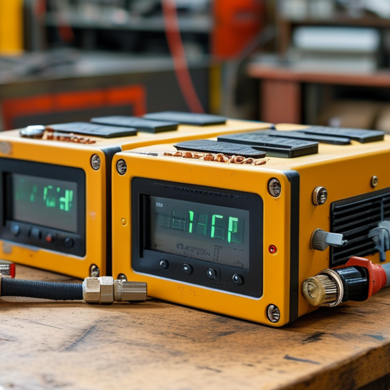
7 Tips for Choosing a TCU Temperature Controller Machine

Define TCU Temperature Range: Water Systems to 300°C Oil Operation

Choosing a TCU Temperature Controller Machine: Water Systems to 300°C Oil Operation

Define the operating medium before comparing temperature controllers. Water offers efficient heat transfer, but temperatures near 300°C require a sealed, pressurized circuit. Check design pressure, expansion volume, relief protection, and sensor placement. Never treat a high-temperature water unit like an ordinary open tank system.

Oil operation demands different decisions. Select a fluid with a suitable flash point, viscosity range, and thermal stability. A pump must maintain steady circulation when oil becomes thick during startup. Inspect seals, hoses, heaters, and heat exchangers for material compatibility. Small leaks can create serious maintenance problems. Keep the working temperature below the fluid supplier’s recommended limit.

Match the machine to the real process load, not only the maximum temperature. Review mold size, product mass, heat-up time, cooling demand, and ambient conditions. Ask for control accuracy at both low and high loads. A fast heater may still perform poorly if the cooling circuit is undersized.

I have seen specifications look impressive while actual recovery was slow. That mistake is easy to make. Choose clear alarms, accessible filters, calibration records, and documented performance tests. Reliable service matters as much as the initial purchase.

Match Heating Capacity and Cooling Load Using kW and kcal/h Ratings

Choosing a TCU temperature controller starts with matching heating capacity and cooling load, not just temperature range. Heating capacity is often listed in kW, while cooling performance may appear in kcal/h. As a practical reference, 1 kW equals approximately 860 kcal/h. The conversion helps, but it is not the whole decision.

Tip 1: Calculate the real process load. Include material weight, heat-up time, mold or vessel mass, circulation losses, and the surrounding room temperature. A 12 kW heater may look sufficient on paper, yet a heavy metal fixture can absorb heat slowly. I have seen sizing errors caused by ignoring startup demand. The temperature reached the target eventually, but production became painfully slow.

Tip 2: Check cooling load at the required operating point. Cooling capacity can fall when the process fluid is hot or ambient conditions are poor. Ask whether the rating uses the same inlet temperature, flow rate, and coolant temperature as your application. Tip 3: Leave a sensible margin, usually around 10–20%, without buying excessive capacity. Oversizing may increase cost, cycling, and control instability. I would also verify the actual pump flow and pressure drop. A powerful heater cannot compensate for weak circulation. Manufacturer data is useful, but measured process conditions are more reliable. Record temperatures at startup, steady operation, and peak production before making the final selection.

7 Tips for Choosing a TCU Temperature Controller Machine: Match Heating Capacity and Cooling Load

Select a Temperature Control Unit by comparing its heating capacity in kW with the required cooling load in kcal/h. For reference, 1 kW is approximately equal to 860 kcal/h. The chart below shows balanced capacity levels for common process-temperature control requirements.

Cooling-load values are converted from kW using 1 kW ≈ 860 kcal/h. Final selection should also consider material heat capacity, flow rate, ambient conditions, insulation, and the required temperature stability.

Verify Temperature Accuracy Within ±0.5°C and Sensor Compatibility

Tip 1: Treat ±0.5°C as a verified system result, not a brochure promise. Ask for calibration data across the full operating range. NIST Technical Note 1297 explains that measurement uncertainty includes the sensor, controller, wiring, and calibration method. A display reading alone proves very little.

Tip 2: Match the sensor input precisely. For Pt100 sensors, IEC 60751:2022 lists Class A tolerance as ±(0.15 + 0.002|t|)°C. At 100°C, that equals ±0.35°C before wiring and controller errors. Thermocouples follow different limits. IEC 60584-1 reports Type K Class 1 tolerance as ±1.5°C or ±0.004|t|, whichever is greater. That may exceed your process target.

Tip 3: Check connection details before purchasing. Confirm RTD wiring, thermocouple type, cold-junction compensation, input range, and signal filtering. In commissioning work, a compatible sensor can still show unstable readings when cable resistance is ignored. Keep a calibrated reference probe beside the process sensor during testing. The comparison may expose installation errors. No checklist is perfect. I would also document ambient temperature, cable length, and stabilization time, because small omissions can weaken an otherwise credible ±0.5°C claim.

Compare Pump Flow, Pressure, and Materials Against Process Requirements

7 Tips for Choosing a TCU Temperature Controller Machine

Compare Pump Flow, Pressure, and Materials Against Process Requirements

Selecting a TCU temperature controller starts with the process, not the machine brochure. Match pump flow to the mold, vessel, or jacket volume. Too little flow creates uneven temperatures and slow heat transfer. Too much flow may increase energy use and stress small channels. Check the pump curve at your operating temperature, not only at room temperature. Viscosity changes can be significant.

Tip 1: Calculate the required flow from heat load and temperature difference. Tip 2: Confirm available pressure after hoses, valves, filters, and narrow passages. A strong pump is not always the right pump. Excess pressure can damage connections or disturb sensitive tooling. Install a flowmeter and pressure gauge when possible. Real readings often challenge the original estimate.

Materials deserve equal attention. Choose wetted components that tolerate the heat-transfer fluid, additives, and operating temperature. Stainless steel can support demanding environments, while compatible seals prevent leakage during repeated thermal cycling. Inspect hose ratings carefully. A hose may handle the temperature but fail under pressure. That detail is easy to miss.

Tip 3: Compare material compatibility using supplier data and fluid safety information. Tip 4: Leave a practical pressure margin, but avoid excessive oversizing. I would recheck this decision after pilot testing. Actual flow may fall below the calculated value because of fouling, bends, or aging seals. Document those changes before approving the final controller.

7 Tips for Choosing a TCU Temperature Controller Machine - Compare Pump Flow, Pressure, and Materials Against Process Requirements

Tip Process Requirement to Define Typical Reference Data Recommended TCU Selection Why It Matters
1. Match the operating temperature Required setpoint, normal operating range, start-up temperature, and maximum allowable temperature. Water-based systems commonly operate from approximately 5°C to 95°C under atmospheric conditions. Pressurized water systems can operate above 100°C. Oil systems are commonly selected for approximately 100°C to 350°C service, depending on the heat-transfer fluid. Choose a temperature range that covers the process with operating margin, while ensuring that the fluid, seals, heater, hoses, and sensors are rated for the maximum temperature. An unsuitable fluid or temperature rating can cause boiling, oxidation, seal damage, unstable control, or reduced equipment life.
2. Size the heating and cooling capacity Product mass, mold or vessel mass, material specific heat, temperature change, cycle time, heat loss, and cooling demand. A basic heating estimate is: Q = m × Cp × ΔT ÷ t. Actual sizing should also include heat losses and the heat released by the process. Cooling capacity may be limited by plant-water temperature and available flow. Select a heater and cooler with sufficient capacity for the required ramp rate and peak process load, rather than sizing only for the final holding temperature. Undersizing produces slow warm-up and recovery. Oversizing may increase cost, cycling, and temperature overshoot if control is not properly tuned.
3. Compare pump flow with circuit resistance Required flow through the mold, jacket, platen, heat exchanger, or reactor, including pipe length, fittings, filters, valves, and narrow passages. Small and medium temperature-control circuits may require approximately 10–80 L/min. Larger or low-resistance circuits can require more than 100 L/min. The required value depends on heat load and the allowable temperature difference across the process. Use the pump curve to verify that the pump can deliver the required flow at the actual system resistance, not only at zero pressure or free discharge. Adequate flow improves heat transfer and reduces temperature gradients. Excessive flow can increase energy use, noise, erosion, and stress on fittings.
4. Check pump pressure and available head Total dynamic head, elevation changes, pressure drop through the process equipment, and the minimum pressure required to prevent flashing or cavitation. Many compact TCU circuits operate with pump discharge pressures of roughly 2–6 bar, while the exact pressure depends on flow, piping, temperature, and component resistance. Pressure is not interchangeable with flow. Select a pump whose operating point falls within the stable portion of its performance curve at the required flow and pressure. Include a safety margin without exceeding the pressure rating of the process circuit. Insufficient pressure causes low flow and poor temperature uniformity. Excessive pressure can damage hoses, seals, molds, jackets, or heat exchangers.
5. Select materials for fluid compatibility Heat-transfer fluid type, operating temperature, additives, water quality, corrosion potential, and cleaning chemicals. Stainless steel wetted parts are commonly used for water circuits because of their corrosion resistance. Carbon steel may be suitable in controlled closed-loop systems. Copper, brass, elastomers, and plastics must be checked for compatibility with the selected fluid and temperature. For clean water or aggressive fluids, consider stainless steel piping, pump components, heater chambers, and heat exchangers. Specify gasket and seal materials separately rather than judging compatibility by metal selection alone. Material incompatibility can lead to corrosion, contamination, leakage, blocked passages, and premature failure of seals or pump components.
6. Verify connection size and hydraulic layout Inlet and outlet size, hose length, pipe diameter, return-line arrangement, drain location, venting, and available installation space. Common connections for compact systems range from approximately ½ inch to 2 inches, but connection size alone does not determine actual flow. Long hoses, sharp elbows, undersized fittings, and restrictive filters increase pressure loss. Keep supply and return lines as short and direct as practical. Match the connection size to the required flow and confirm that the piping pressure rating exceeds the maximum pump pressure and operating temperature. A poor layout can make a correctly sized pump perform like an undersized pump and can create air pockets, unstable flow, or difficult maintenance access.
7. Confirm control accuracy and protection functions Required temperature tolerance, sensor position, response time, alarm limits, pressure limits, and process safety requirements. Many industrial applications target control stability around ±0.5°C to ±1.0°C, although actual performance depends on sensor location, heat load, flow, insulation, and controller tuning. Specify a calibrated process sensor, high-temperature cutout, low-level protection, overpressure protection, pump overload protection, leak detection where needed, and alarms for inadequate flow or cooling water. Protection functions reduce the risk of product defects, heater damage, dry running, unsafe pressure, overheating, and unplanned downtime.

Reference note: Flow, pressure, temperature range, and material recommendations are indicative engineering ranges. Final selection should be based on the equipment datasheet, pump curve, heat-transfer-fluid supplier data, piping calculations, and the process manufacturer’s pressure and temperature limits.

Assess Safety Standards, Energy Efficiency, Controls, and Maintenance Access

7 Tips for Choosing a TCU Temperature Controller Machine

Assess Safety Standards, Energy Efficiency, Controls, and Maintenance Access

A reliable TCU temperature controller should meet recognized electrical and pressure safety standards. Ask for test reports, protective functions, and clear operating limits. Check emergency stops, over-temperature protection, leak detection, and guarded hot surfaces. Small details matter.

Review the heating and cooling efficiency under your actual process load. A low energy label alone can mislead. Compare standby consumption, insulation quality, response time, and heat recovery options. Select a pump that matches the circuit instead of choosing excessive capacity. Oversizing can increase energy use and reduce control stability. Keep records.

Controls should show temperature, pressure, flow, alarms, and operating history clearly. Touchscreens are useful, but physical emergency controls remain valuable during faults. Confirm sensor accuracy and calibration procedures before purchase. Remote access may improve supervision, yet it can also create cybersecurity concerns. Do not ignore them.

Maintenance access often determines the machine’s real operating cost. Inspect panel layout, drain points, filters, valves, and electrical terminals. Technicians should reach routine service parts without dismantling half the unit. I once underestimated this issue, and a simple filter replacement caused unnecessary downtime. Ask how replacement parts are identified and supported. Leave space around the machine for tools, ventilation, and safe inspection.

Download
Brochure