Empowering Engineering Excellence: Innovate, Elevate, Deliver.

How to Choose an Outdoor Isolator Switch in 2026?

How to Choose an Outdoor Isolator Switch in 2026?

Outdoor electrical systems are expanding quickly. IRENA reported 473 GW of renewable capacity added worldwide in 2023. Solar farms, battery sites, and commercial equipment now face harsher outdoor conditions.

The IEA’s Electricity 2024 report also projects strong global electricity demand growth through 2026. This growth increases the need for safe, accessible isolation points. Choosing an Outdoor Isolator Switch is not simply a current-rating exercise. It requires practical judgment.

Weather changes everything.

A coastal installation may expose contacts to salt mist. A rooftop unit may face intense ultraviolet radiation, dust, and standing water. IEC 60529 ingress ratings help assess enclosure protection. IEC 60947-3 supports the selection of switch-disconnectors for low-voltage applications.

NFPA President Jim Pauley has stated, “Electrical safety is everyone’s responsibility.” That principle applies before installation, not only during emergencies. A suitable switch should match voltage, load current, pole configuration, fault conditions, operating frequency, and isolation requirements.

Look closely at the handle. Can a technician operate it while wearing gloves? Can it accept a lock? Is its position visible from several metres away? These details often matter more than a polished product label.

There is no universal best model.

A higher IP rating may not solve condensation problems. A larger enclosure may still fail without proper cable glands. Manufacturer declarations, test certificates, temperature limits, and maintenance guidance deserve careful review.

This guide compares those factors for 2026 applications. It also questions a common assumption: outdoor equipment is safe merely because it is weatherproof. Real reliability depends on the switch, its installation, and the environment working together.
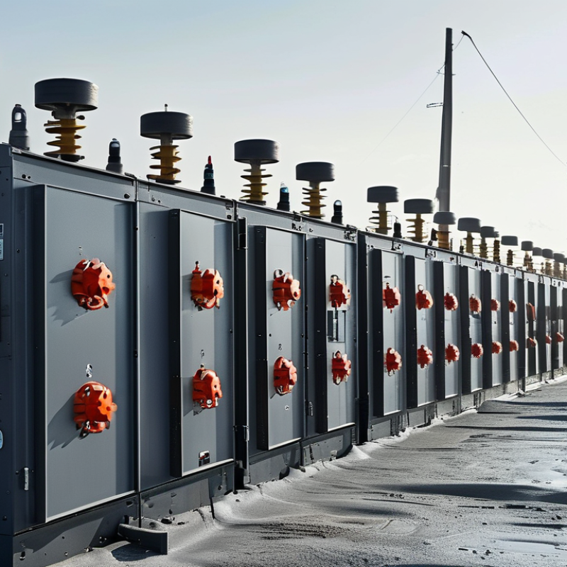
How to Choose an Outdoor Isolator Switch in 2026?

What Is an Outdoor Isolator Switch and Why Is It Needed?

An outdoor isolator switch is a manually operated device that disconnects electrical equipment from its supply. It creates a visible, local isolation point for inspection, maintenance, or emergency shutdown. Unlike an indoor switch, it must withstand rain, dust, sunlight, temperature changes, and accidental contact. It is commonly installed beside outdoor motors, heat pumps, battery systems, and solar inverters.

The need is growing. The International Energy Agency’s Renewables 2024 report projects almost 5,500 gigawatts of new renewable capacity between 2024 and 2030. Solar power represents most of this expansion. More outdoor equipment means more exposed connection points. A correctly rated isolator helps technicians work with clearer boundaries and fewer avoidable risks. It does not replace proper circuit protection.

Selection requires practical judgment. Check the rated voltage, current, switching category, pole arrangement, and enclosure rating. IEC 60529 defines IP protection levels; an IP66 enclosure, for example, resists powerful water jets and dust ingress. IEC 60947-3 also covers switch-disconnectors used in low-voltage circuits. Match the switch to the actual load, not only the cable size.

Look closely at the installation site. A rooftop may need UV resistance, corrosion protection, and a lockable handle. A coastal site needs more attention to salt exposure. Small details matter. Yet specifications can be misleading. “Weatherproof” alone is not a sufficient engineering description. Review fault conditions, cable entry, operating temperature, and maintenance access before choosing the final device.

Which Electrical Ratings Should an Outdoor Isolator Switch Meet?

How to Choose an Outdoor Isolator Switch in 2026?

An outdoor isolator switch must match the circuit, not just the equipment label. Check the rated operational voltage, current, frequency, and number of poles. The switch should safely disconnect every required live conductor. For motor-driven loads, review the utilization category, such as AC-22A or AC-23A. A simple resistive-load rating may be unsuitable for compressors or pumps. This mistake is easy to make.

Short-circuit performance also matters. Compare the switch’s conditional short-circuit rating with the prospective fault current at the installation point. Confirm coordination with the upstream protective device. The enclosure should provide an appropriate IP rating for rain, dust, and water jets.

Outdoor sunlight can weaken plastics over time, so verify UV resistance and the declared temperature range. Cold mornings and hot enclosures are both real conditions.

Mechanical details support electrical safety. Look for a clear isolating position, reliable padlocking, and terminals suitable for the cable size. Check insulation voltage and creepage requirements when moisture or pollution is expected.

I also recheck derating for high ambient temperatures, even when the catalog value looks generous. It is not always generous in practice.

Installation must follow the applicable local electrical rules and the manufacturer’s instructions. A qualified electrician should verify the final selection, fault level, and test results before energizing the circuit.

How to Select the Right Enclosure and Weather Protection

When choosing an outdoor isolator switch in 2026, treat the enclosure as seriously as the electrical rating. IEC 60529 classifies protection against dust and water, but an IP66 rating does not guarantee long-term resistance to sunlight, salt, or condensation. The 2023 State of the Climate report recorded exceptional global heat and widespread extreme weather, making exposed equipment less predictable. A shaded wall still receives reflected ultraviolet radiation.

Match the enclosure to the site, not only the catalogue. Use UV-stabilised material or coated metal near open roofs and coastal areas. Select corrosion-resistant hardware where salt spray is common. A gasket should compress evenly, while cable entries should face downward and include suitable glands. Small drainage details matter.

They are often overlooked.

For heavy rain, consider IP66 or IP67 protection, but verify the manufacturer’s test conditions. NEMA 250 Type 3R addresses outdoor rain, while Type 4 provides stronger protection against hose-directed water. Neither classification alone solves internal condensation. A pressure-equalising vent or controlled drainage path may be necessary in areas with sharp temperature changes. The 2024 World Meteorological Organization climate report highlights continuing weather volatility, yet local exposure still matters more than a global average.

In field inspections, I have seen excellent enclosures fail because water entered through poorly tightened glands. I have also seen oversized boxes collect moisture. The practical choice is sometimes less obvious. Check the installation height, cleaning method, sunlight direction, and maintenance access before final selection.

How to Match the Switch to Your Outdoor Installation

How to Choose an Outdoor Isolator Switch in 2026?

Matching an isolator switch to the installation starts with the load, not the enclosure. Check the equipment’s rated voltage, operating current, poles, and switching category. A motor, pump, or heat pump may draw a higher starting current. The switch must tolerate that demand without nuisance failures. Leave sensible capacity, but avoid careless oversizing. An oversized switch can make cable termination awkward and inspection less clear.

Study the location closely. A wall-mounted unit under a roof needs different protection from a switch beside a pool or coastal plant room. Look for an enclosure rating suitable for dust and water exposure, plus resistance to sunlight and temperature changes. Cable glands should match the cable diameter and maintain the enclosure seal. Condensation is easy to overlook. It may collect inside after a cold night.

Think about access and isolation during maintenance. The handle should remain visible, reachable, and clearly marked without standing in pooled water. A lockable mechanism can prevent accidental re-energizing while someone works on the equipment. Confirm the mounting surface, cable route, terminal size, and earthing arrangement before purchase. Local electrical rules still control the final choice, so a qualified electrician should verify the installation. A tidy fit is not always a safe fit. Recheck torque settings and weather seals after installation.

How to Choose an Outdoor Isolator Switch in 2026?

Match the switch enclosure to the installation’s exposure level. The chart uses IEC 60529 IP-code digits as a practical starting point: the first digit indicates protection against solid objects and dust, while the second digit indicates protection against water.

Selection guide: A sheltered outdoor location may suit an IP44 target, while exposed installations commonly require stronger protection such as IP55. Areas subject to frequent washdown should be assessed around IP66, and locations with a temporary immersion risk may require IP67. Confirm the final enclosure rating, switching capacity, temperature range, UV resistance, cable-entry system, and local electrical-code requirements before installation.

What Safety Checks Are Needed Before and After Installation?

Before choosing an outdoor isolator switch in 2026, match its voltage, current rating, and number of poles to the circuit. Check the enclosure’s weather protection rating, UV resistance, and corrosion resistance. Coastal air, dust, and direct sunlight can shorten service life. Follow applicable electrical rules and the installation instructions.

Only a qualified electrician should complete the work. Before installation, isolate the supply and secure it against reconnection. Prove the circuit is dead with an approved tester, then test the tester again. Inspect cables for cuts, moisture, and brittle insulation. Confirm that the mounting surface is solid and that cable glands fit tightly. The earth conductor needs a reliable termination. Do not rely on appearance.

After installation, check every terminal for correct torque. Loose connections create heat. Verify polarity, earth continuity, insulation resistance, and switch operation before energising the circuit. Confirm that the isolator disconnects all required live conductors. Inspect the cover, gasket, glands, and unused entries for complete sealing. A small gap can admit water during heavy rain. Test the connected equipment under normal load, then check for unusual warmth, noise, or smell. Record the test results and label the isolator clearly. Even experienced installers can miss one detail, especially when weather changes or access is awkward. Recheck the enclosure after the first wet week.

How to Choose an Outdoor Isolator Switch in 2026? - What Safety Checks Are Needed Before and After Installation?
Category Selection or Safety Check Recommended Requirement or Acceptance Criterion Verification Method When to Check
Electrical Rating Rated operational voltage (Ue) The switch rating must be equal to or higher than the system voltage. Confirm compatibility with the applicable AC or DC circuit and the installation design. Compare the switch nameplate and technical documentation with the project drawings and supply characteristics. Before selection
Electrical Rating Rated current (Ie) The rated current must be suitable for the connected load and must not be lower than the circuit design current. Allow for continuous-load requirements, ambient temperature and enclosure derating. Check the design current, protective-device coordination and the switch nameplate rating. Before selection
Switch Function Isolation and switching duty Use a device designed for isolation where safe disconnection is required. Confirm the required utilization category and whether the switch will interrupt motor, heater, photovoltaic or other inductive loads. Review the circuit purpose, load type, applicable product standard and manufacturer rating table. Before selection
Number of Poles Pole configuration Select the pole arrangement required by the system design. For single-phase circuits, simultaneous switching of live conductors may be required; neutral switching must follow local wiring rules and design requirements. Compare the wiring diagram, supply earthing arrangement and local electrical regulations with the product configuration. Before selection
Outdoor Protection Ingress protection rating Choose an enclosure with an IP rating appropriate for the location. The required rating depends on exposure to rain, dust, hose-directed water, condensation and the mounting position; IP ratings do not replace correct installation. Assess the site conditions and verify the enclosure marking against the relevant IP classification requirements. Before selection
Outdoor Protection UV, corrosion and temperature resistance Materials, seals and labels must be suitable for the local sunlight, humidity, salt exposure, chemicals and operating-temperature range. Avoid unapproved modifications that can reduce weather resistance. Review the technical data and inspect the proposed mounting location for environmental hazards. Before selection
Mechanical Safety Lockable handle and clear position indication The handle should clearly indicate ON and OFF positions and support an appropriate lockout method when required. The mechanism must operate smoothly without excessive force. Operate the handle with the circuit isolated and confirm the position marking, locking feature and mechanical interlock. Before and after installation
Installation Location Accessibility and safe isolation point Install the switch where it is readily accessible for operation and maintenance, away from standing water, avoidable impact and obstruction. Maintain required working clearances. Inspect the mounting height, access route, clearance, visibility and proximity to the equipment being isolated. Before installation
Installation Quality Cable entry, glands and sealing Cable glands, blanking plugs and seals must be compatible with the enclosure and cable diameter. Cable entries must prevent water ingress and avoid mechanical strain on terminals. Visually inspect entries and confirm that unused openings are sealed. Check cable support and gland tightness according to the installation instructions. After installation
Wiring Terminal connection and conductor identification Conductors must be connected to the correct terminals, with insulation intact and no exposed copper beyond the terminal. Protective conductors must not be switched or disconnected contrary to the wiring rules. Perform a visual inspection and verify conductor identification against the wiring diagram. Check terminal tightness using the specified tightening method. After installation
Earthing and Bonding Protective bonding and continuity All required exposed-conductive parts and metallic components must be correctly bonded. Protective-conductor continuity must be confirmed before energization. Use an approved continuity tester and record results in accordance with the applicable installation standard. After installation
Insulation Insulation resistance The measured insulation resistance must meet the minimum value required by the applicable local standard and equipment instructions. Sensitive electronic equipment may need to be disconnected before testing. Test with a suitable insulation-resistance instrument using the test voltage specified by the applicable standard. After installation
Polarity and Function Correct polarity and all-pole operation Conductors must be correctly identified and the intended live conductors must disconnect together where required. The OFF position must remove supply from the intended isolated equipment. Carry out polarity, functional and dead-circuit checks with calibrated test equipment. After installation
Protection Coordination Short-circuit and overload protection The upstream protective device must protect the conductors and isolator against overload and prospective short-circuit current. Confirm that the switch breaking and conditional ratings are adequate. Compare fault-current calculations, protective-device settings and equipment ratings with the installation design. Before energization
Functional Test ON/OFF operation under safe conditions The switch must operate smoothly, latch correctly and control the intended circuit. There should be no abnormal heating, noise, arcing or visible damage during the test. Follow the approved commissioning procedure and observe the switch during controlled operation. After installation
Labelling Circuit identification and warning labels Labels must identify the equipment or circuit controlled, the isolating position and any relevant electrical hazards. Labels must remain legible and weather-resistant. Inspect labels from the normal approach position and confirm they match the distribution schedule and drawings. After installation
Commissioning Records Test results and documentation Record inspection results, test measurements, circuit identification, protective-device details and any deviations. Keep documentation available for future maintenance. Complete the electrical installation certificate, inspection checklist or commissioning record required by the project and local regulations. After testing
Maintenance Periodic visual and operational inspection Check for cracked enclosures, damaged seals, corrosion, loose glands, faded labels, water ingress, overheating and stiff operation. Remove the circuit from service if a safety defect is found. Perform a documented inspection at an interval based on the environment, risk assessment and local maintenance requirements. During service
Safety note: Installation, testing and maintenance should be carried out by a competent person using safe isolation procedures, suitable test instruments and the electrical regulations applicable to the installation location. Never rely on the switch position alone to prove that a circuit is dead.
Download
Brochure