Empowering Engineering Excellence: Innovate, Elevate, Deliver.
Choosing among the 7 best vacuum coating machines for industrial buyers starts with the coating job, not the brochure. A vacuum coating machine must suit the substrate, target film, production volume, and available floor space. A glossy sample is useful. It is not enough.
Donald M. Mattox, a respected author on physical vapor deposition, has written extensively about PVD processes and their practical requirements. A useful paraphrase of that approach is: “Match the deposition process to the coating, substrate, and production target.” This is a paraphrase, not a verbatim quotation. In practice, buyers should compare chamber size, pumping capacity, process controls, service access, and compatibility with their materials. Picture a technician loading a batch of metal components: awkward fixtures or slow pump-down cycles can affect daily output. Details matter.
The right choice depends on the application. Optical films, decorative finishes, and wear-resistant coatings may call for different process configurations. Ask vendors for sample runs, process documentation, and clear service terms. Check what the machine can repeat, not only what it can achieve once. Small caveat. Published specifications do not always reflect a buyer’s actual parts or workflow. This guide compares seven options through practical selection criteria, while recognizing that the best machine on paper may not be the best fit on the factory floor.
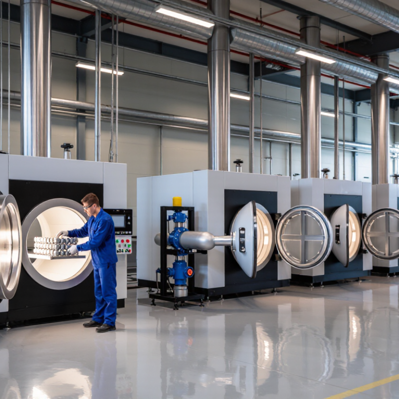
Industrial vacuum coating machines create a controlled, low-pressure space so coating atoms can travel with fewer collisions. A typical system uses a sealed chamber, mechanical and high-vacuum pumps, pressure gauges, a substrate holder, and a deposition source. Operators clean and load the parts, evacuate the chamber, then introduce a measured process gas or heat a solid coating material. In sputtering, plasma ions knock atoms from a target; in evaporation, heat turns source material into vapor. The atoms cross the chamber and condense on cooler surfaces. Small details matter. Fingerprints can weaken adhesion.
Pressure changes the journey. Leybold’s Fundamentals of Vacuum Technology gives an air mean free path of roughly 68 nanometers near atmospheric pressure. Using its inverse relationship with pressure, that distance approaches 0.7 meters at 10⁻⁴ millibar. This is an estimate, not a universal machine setting: coating recipes often use higher working pressures after process gas enters. Engineers balance gas pressure, power, part spacing, and rotation to achieve an even film. A shadowed recess may still coat poorly. That is easy to miss. The U.S. Department of Energy’s thin-film manufacturing assessments also identify material use and process control as important production considerations; in practice, fixture design and chamber cleanliness can decide whether a batch meets thickness targets.
Vacuum coating machines differ mainly in how they create and deposit a thin film. Thermal evaporation heats a source until its material vaporizes, then condenses it onto a substrate. It suits many optical and decorative coatings, but its line-of-sight process can leave shadowed areas on complex parts. Not interchangeable.
Chemical vapor deposition forms films through reactions between gases inside a chamber. Plasma-enhanced CVD can lower the heat required, which helps with temperature-sensitive substrates. Atomic layer deposition repeats controlled surface reactions to build exceptionally thin, even layers, though its cycle time may limit output. These methods are not always direct substitutes: film chemistry, part geometry, and production volume all affect the choice.
The scale of advanced manufacturing offers useful context. SEMI reported worldwide semiconductor manufacturing equipment sales of $117.1 billion in 2024 , up 10% from 2023. That figure covers many equipment categories, not coating machines alone. Buyers should compare film uniformity, substrate temperature, chamber capacity, cycle time, and maintenance needs against their own process targets. A high-spec chamber can still be a poor fit. Published market totals rarely reveal the operating details that decide whether a coating line performs reliably.
Industrial buyers can compare seven vacuum coating machine types by substrate, coating function, throughput, and maintenance needs. Thermal evaporation suits simple metal films on heat-sensitive parts. E-beam evaporation handles high-melting-point materials, but needs careful source control. Magnetron sputtering offers dense, adherent coatings for tools, glass, and components. Ion-beam sputtering favors precise optical layers, often at lower production speeds.
PECVD deposits functional films at comparatively low substrate temperatures. ALD builds exceptionally uniform, ultrathin layers, though cycle times can limit output. Roll-to-roll vacuum coaters process flexible webs continuously, with tension control and web handling central to quality. These categories overlap: some describe deposition methods, others describe production layouts. That distinction matters. A polished specification sheet may still hide downtime or poor yield.
These figures indicate scale in adjacent sectors, not direct demand for coating machines. Buyers should verify performance using their own substrates and target films. Check chamber footprint, pump-down time, coating uniformity across the usable area, and service intervals. Pilot runs can expose awkward problems, including edge defects or slow changeovers.
Vacuum coating machines support semiconductor wafers, optical lenses, architectural glass, and wear-resistant tools. Each application demands a different balance of film thickness, adhesion, and production speed. A lens line may need consistent antireflection layers across curved surfaces; a tool shop may prioritize hard, durable coatings. Small details matter. Chamber layout, fixture rotation, and substrate cleaning can affect results as much as the deposition source. IEA PVPS estimated that global photovoltaic capacity exceeded 1.6 terawatts in 2023, expanding demand for reliable thin-film manufacturing processes (Trends in Photovoltaic Applications 2024).
Industrial buyers should compare usable chamber volume, batch size, pump-down time, coating uniformity, and maintenance access. These figures need testing with actual parts, not just brochure samples. SEMI’s 2024 forecast projected worldwide semiconductor manufacturing equipment sales of 109.1 billion dollars in 2025, reflecting continued investment across processes that include thin-film deposition. Yet a larger market does not guarantee a suitable machine. Ask suppliers for repeatability data, cycle-time measurements, and evidence from comparable substrates. Check how quickly technicians can replace shields and clean fixtures. A high nominal throughput can disappoint when changeovers are frequent. One uncomfortable question remains: will the coating stay consistent after months of production, not merely during acceptance testing?
| Machine Type | Typical Industrial Applications | Deposition Process | Typical Pressure Range | Key Performance Factors | Best Fit |
|---|---|---|---|---|---|
| Batch Thermal Evaporation System | Decorative metallization, reflectors, optical components, and thin-film layers on small or medium-sized parts. | A heated source evaporates material, which condenses on substrates inside a vacuum chamber. | High-vacuum deposition; base pressures are commonly in the 10−5 to 10−6 mbar range, depending on system design and process. | Chamber capacity, source-to-substrate geometry, film-thickness control, material utilization, and batch-to-batch repeatability. | Buyers needing a relatively straightforward batch process for evaporatable materials and moderate production volumes. |
| Electron-Beam Evaporation System | Optical coatings, wear-resistant layers, semiconductor-related films, and deposition of high-melting-point materials. | An electron beam heats and evaporates material from a source; vapor travels to and condenses on substrates. | Typically high vacuum, often around 10−5 to 10−7 mbar before deposition; the operating pressure depends on the process. | Beam power and stability, source capacity, substrate heating, thickness monitoring, film uniformity, and control of reactive-gas delivery when used. | Applications that require evaporation of refractory materials or flexible control over multilayer optical stacks. |
| Magnetron Sputtering System | Decorative and functional coatings, display and sensor layers, architectural glass coatings, and metal or compound films. | Plasma ions strike a target and eject atoms that form a coating on the substrate; reactive gases may be added to produce compounds. | Base pressure is commonly near 10−6 to 10−7 mbar; sputtering often runs around 10−3 to 10−2 mbar. | Target utilization, power density, deposition rate, plasma stability, substrate temperature, coating uniformity, and reactive-process control. | Production requiring dense, adherent films and a broad choice of metallic or compound coating materials. |
| Inline Magnetron Sputtering Coater | Large-area architectural glass, solar-related glass products, and other flat substrates produced in a continuous or indexed line. | Substrates travel through successive vacuum chambers or zones equipped with sputtering sources. | Vacuum levels and sputtering pressures vary by zone; sputtering zones commonly operate around 10−3 to 10−2 mbar. | Line speed, usable coating width, chamber layout, source configuration, uptime, layer-to-layer repeatability, and maintenance access. | High-throughput operations coating large flat panels with repeatable multilayer stacks. |
| Roll-to-Roll Web Coating System | Flexible packaging films, barrier and decorative films, flexible electronics substrates, and metallized polymer webs. | A continuous web unwinds, passes through a vacuum deposition zone, and rewinds; evaporation or sputtering sources may be used. | High-vacuum deposition is typical; operating pressure depends on the source and process, while the web path is maintained under controlled vacuum. | Web speed and tension, coating width, winding quality, deposition uniformity, defect rate, substrate temperature, and roll-to-roll yield. | Continuous production on flexible materials where throughput and web handling are critical. |
| Ion-Assisted Evaporation System | Precision optical filters, lenses, laser optics, and coatings requiring improved density or environmental durability. | Evaporated material is deposited while an ion source simultaneously or intermittently bombards the growing film. | Typically a high-vacuum process; pressure is set to support evaporation and the selected ion-assist conditions. | Ion energy and current, substrate temperature, film stress, refractive-index consistency, layer-thickness accuracy, and optical monitoring. | Optical production where film density, adhesion, and repeatable optical properties are important. |
| Atomic Layer Deposition (ALD) System | Conformal coatings on complex 3D parts, semiconductor structures, powders, and components requiring very thin functional films. | Alternating, self-limiting precursor exposures build a film in controlled surface-reaction cycles. | Often operated at low pressure, commonly from fractions of a mbar to several mbar; the applicable range depends on the reactor and chemistry. | Cycle time, precursor delivery, temperature window, conformality, film thickness per cycle, chamber cleanliness, and precursor handling. | Applications needing precise, conformal, nanoscale films on high-aspect-ratio or intricate surfaces. |
Choosing a vacuum coating machine starts with the part, not the price tag. Identify the substrate, target coating, and required production volume. A small component may fit a compact chamber, while long panels need more usable space and careful fixture planning. Check the chamber’s actual working dimensions, not only its external size.
Then compare process capabilities. Confirm that the machine supports your coating material and required method, such as thermal evaporation or sputtering. Review pump-down time, pressure range, temperature control, and coating uniformity across a loaded chamber. Ask for test results using representative parts. A polished specification sheet can still hide a poor fit. I would not choose on price alone; that can be an expensive shortcut. Also consider maintenance access, operator training, spare-part availability, and the supplier’s technical support. Some details are easy to overlook.
Tips: Bring sample parts and a written quality target to supplier discussions. Ask how results are measured and what routine upkeep involves. Leave room for uncertainty; your first production run may reveal a requirement you missed.