Empowering Engineering Excellence: Innovate, Elevate, Deliver.
Choosing an analog-to-digital converter is about more than resolution. The right device must capture a real signal accurately and deliver data at a useful speed. A practical Analog Converter choice also depends on input range, channel count, power use, and the interface your system supports. Small mismatches can add noise, waste energy, or complicate a circuit board. Details matter.
This guide introduces ten ADC options for buyers in 2026, spanning different needs and levels of complexity. It considers key specifications, including sampling rate, bit depth, input configuration, and available support documentation. A battery-powered sensor may need low current draw and modest data rates. An audio setup may prioritize clean sampling and low distortion. Industrial measurements can call for stable performance across changing conditions. One device rarely suits every job.
Treat the list as a starting point, not a lab verdict. A polished specification sheet can still hide practical trade-offs. Check the datasheet, confirm compatibility with your signal source, and review evaluation-board results where available. Pay attention to voltage references and input-driving requirements; these can shape performance as much as the converter itself. Your actual design may reveal an overlooked constraint. That is worth admitting early. The best choice is the one that fits your measurements, budget, and build—not simply the highest number on a product page.
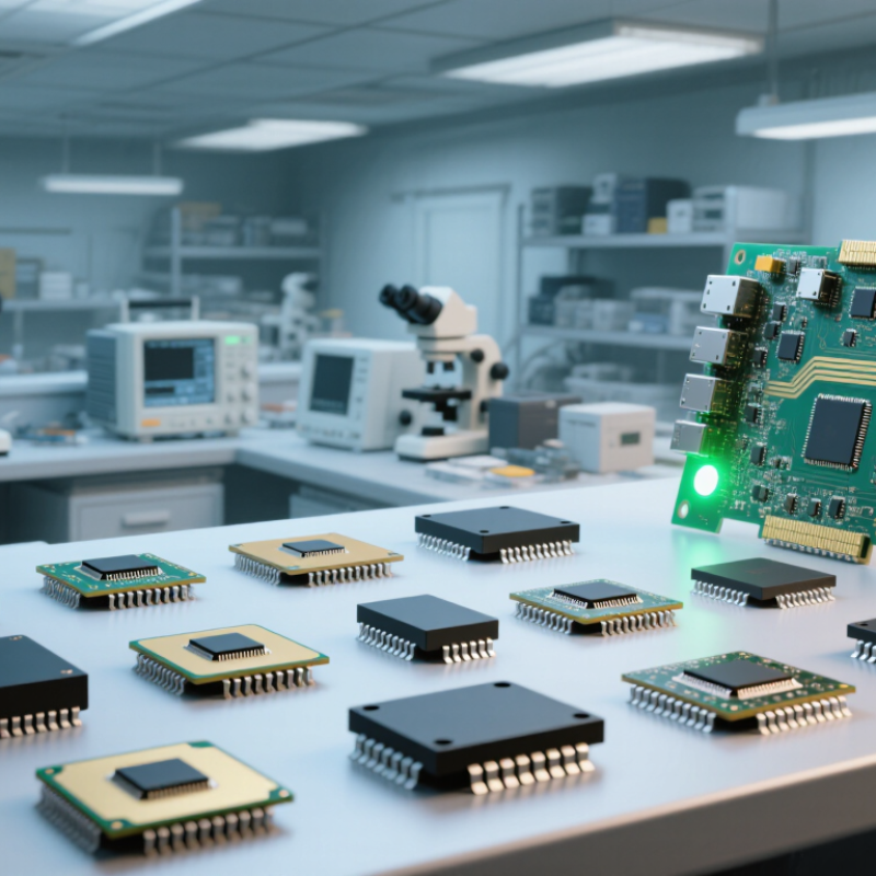
An analog-to-digital converter turns changing voltages into numbers a processor can store and interpret. A microphone produces a tiny, rapidly varying signal; a temperature sensor may change far more slowly. The ADC samples that voltage at set intervals, then assigns each sample a digital value. More samples per second can preserve faster changes, but only when the rest of the circuit supports them.
The input signal also needs suitable conditioning. A filter can reduce unwanted high-frequency noise before sampling, while a stable voltage reference helps keep readings consistent. In a practical logger, a loose sensor wire or noisy power supply may cause more trouble than the converter’s advertised bit depth.
Tiny changes matter.
Higher resolution can reveal finer steps, but it cannot remove noise already present in the signal. Buyers should match the input range, sampling rate, resolution, and interface to the sensor and task. It is easy to overlook the wiring. Real measurements rarely behave as neatly as a datasheet graph.
An ADC’s resolution is only a starting point. A 16-bit converter can represent many levels, but electrical noise may leave far fewer bits useful in practice. Check effective number of bits and signal-to-noise performance under conditions close to your own design. Numbers can mislead. A quiet laboratory input is not the same as a sensor beside a switching motor. Sampling rate matters too, but so does input bandwidth: a fast clock cannot preserve frequencies the analog front end has already weakened. Allow room for the signal’s highest frequency and its filtering needs.
Input range should match the sensor output, so a tiny voltage does not occupy only a small part of the converter’s range. Look at reference-voltage stability, channel count, power draw, and interface timing; each can affect accuracy or system complexity. For example, a battery-powered logger may favor low energy use, while a vibration monitor may need rapid sampling and predictable latency. Read how specifications were measured, and test a candidate with the actual source impedance and board layout where possible. I have seen a neat datasheet comparison become less useful once cable noise and grounding entered the setup. That is an imperfect shortcut, but a practical warning: compare the whole signal path, not one headline number.
| Profile | Resolution | Maximum Throughput | Channel Configuration | Converter Architecture | Input and Interface | Best Suited For |
|---|---|---|---|---|---|---|
| 01 — Low-Speed Precision | 16 bit | 860 samples/s | 4 multiplexed inputs | Delta-sigma | Programmable gain amplifier; I²C | Slow sensor readings, temperature measurement, and compact microcontroller projects |
| 02 — Faster Sensor Sampling | 12 bit | 3,300 samples/s | 4 multiplexed inputs | Delta-sigma | Programmable gain amplifier; I²C | Low-cost sensor acquisition where a higher sample rate matters more than 16-bit resolution |
| 03 — High-Resolution Industrial | 24 bit | Up to 30,000 samples/s | 8 single-ended or 4 differential inputs | Delta-sigma | Multiplexer and programmable gain amplifier; SPI | Precision weighing, process instrumentation, and low-bandwidth measurement systems |
| 04 — Simultaneous Industrial I/O | 16 bit | Up to 200,000 samples/s per channel | 8 simultaneous-sampling channels | SAR | Selectable ±5 V or ±10 V input ranges; serial or parallel interface | Motor control, power monitoring, and systems that need synchronized channel sampling |
| 05 — High-Speed Multichannel I/O | 16 bit | Up to 1,000,000 samples/s per channel | 8 simultaneous-sampling channels | SAR | Selectable ±5 V or ±10 V input ranges; serial or parallel interface | Fast control and data-acquisition equipment using multiple synchronized voltage inputs |
| 06 — Precision Single-Channel | 18 bit | Up to 2,000,000 samples/s | 1 differential input | SAR | Differential analog input; SPI-compatible serial interface | High-accuracy, high-speed measurement when one channel is sufficient |
| 07 — Dual-Channel High-Speed | 16 bit | Up to 4,000,000 samples/s per channel | 2 simultaneous-sampling channels | SAR | Differential inputs; serial interface | Synchronized waveform capture and compact, high-throughput measurement designs |
| 08 — Wideband Data Acquisition | 16 bit | Up to 130,000,000 samples/s | 1 channel | Pipelined | Differential input; selectable LVDS or CMOS parallel output | Wideband instrumentation and communications systems requiring 16-bit conversion |
| 09 — Dual-Channel Wideband | 12 bit | Up to 250,000,000 samples/s per channel | 2 channels | Pipelined | Differential inputs; LVDS output | High-speed communications, imaging, and multi-channel waveform digitization |
| 10 — High-Speed RF Sampling | 14 bit | Up to 1,250,000,000 samples/s per channel | 2 channels | Pipelined | Differential inputs; JESD204B serial data interface | RF and broadband systems that need very high sampling rates and a high-speed serial output |
| These entries summarize representative converter specifications, with manufacturer and product names omitted. Maximum throughput is a headline rating; achievable performance depends on operating conditions, input frequency, clock quality, circuit layout, and interface configuration. Confirm the exact datasheet and package variant before purchase. | ||||||
An analog-to-digital converter, or ADC, turns a changing voltage into numbers a processor can use. The right type depends on signal speed, required detail, and acceptable delay. A slow temperature probe has different needs from a fast video signal. Fit matters more. A higher bit count alone does not guarantee better measurements; noise, input range, and circuit layout matter too.
Successive-approximation ADCs suit control systems and many sensor measurements, offering a useful balance of speed and resolution. Sigma-delta converters are often a strong match for audio and precise, slower measurements, where fine detail matters more than low latency. Pipeline converters handle high-throughput signals, such as video or communications inputs, but introduce conversion delay. Flash converters are extremely fast, though they typically consume more power. Dual-slope designs can provide stable readings in handheld measurement equipment, with slower updates as the trade-off. A clean spec sheet can still mislead.
Tips: Match the converter to the full signal chain. Check sample rate, effective resolution, input voltage range, and reference stability. For a sensor beside a small motor, electrical noise may matter more than headline resolution. Test with the actual signal source when possible. Check the whole chain.
Typical resolution ranges by ADC architecture. Flash converters are suited to very high-speed signals; integrating and sigma-delta designs favor precision at lower bandwidths. SAR and pipeline architectures cover a broad range of general-purpose and high-speed applications.
Ranges are representative architecture-level values, not guaranteed specifications. Actual resolution and performance depend on the individual converter and operating conditions.
Ten notable analog-to-digital converters for buyers in 2026 are best compared by the work they must do, not by headline resolution alone. A low-power SAR converter suits battery sensors that sample occasionally. A precision delta-sigma design can help with slow, low-level measurements. Pipeline converters favor fast data capture, while RF-sampling units handle wide input bandwidths. Audio converters prioritize clean sound across the audible range. Multichannel simultaneous-sampling models keep phase relationships aligned. Multiplexed converters reduce component count when channels need not be sampled together. Isolated converters add separation between measurement and control circuits. Sensor-ready converters may include amplification or reference support. Evaluation-board versions help buyers test a circuit before committing.
These options involve trade-offs. More bits do not automatically mean more accurate readings; noise, reference stability, layout, and input range matter too. Check the datasheet’s effective resolution and sampling conditions, then test with the sensor and signal path you plan to use. A specification measured in ideal conditions may not match a crowded board. I have seen that detail overlooked.
Tips: Match input range to the real signal, leave headroom for spikes, and inspect interface compatibility. If unsure, compare two evaluation setups. It is worth the extra time.
Choosing an ADC starts with the signal, not the headline bit count. Measure its bandwidth, voltage range, source impedance, and expected noise. A 16-bit part can be wasteful if the sensor is noisy; a 12-bit converter may be enough after sensible filtering. Check effective number of bits (ENOB), not resolution alone. They are not the same.
Choose a sampling speed with margin. For a 20 kHz signal, sampling just above 40 kS/s meets only basic Nyquist conditions; practical filtering usually needs more room. Decide whether you need single-ended or differential inputs, then check input settling, reference stability, and interface compatibility.
Tiny detail, big impact. A weak reference or long PCB trace can erase gains on paper. Price the supporting circuit, power use, and software effort, not just the converter. For battery devices, low-power operation may matter more than peak speed.
For audio or vibration work, timing jitter and channel synchronization deserve attention. It is easy to overbuy. Compare a few realistic candidates using the same signal source, filter, and measurement setup. Datasheet figures help, but the final choice depends on the board and sensor. Leave budget for evaluation and calibration; that cost is often missed.